Notes on programming

With apologies to Paganini

This is what happens when you feed a MIDI file of Paganini's Capriccio no. 24 to a monosynth built with MRG modules:

I find that violin, viola and cello compositions are perfect to test a simple monosynth, as they are mostly monophonic and they range across many octaves.

The Capriccio n.24 is perfect in this, and it actually overstretches the octaves over the limits of my 2HP MIDI module: unfortunately all sounds above C7 are flattened to C7. But it's still a good demo of the MRG 3340 VCO's excellent 1V/O tracking.

I played a lot with the envelope generated by the MRG 3310 ADSR module. The envelope is actually fed to the 24db MRG LPF, that acts as a low pass gate. You can see me tweaking the filter as well. The output of the filter is then passed to the MRG VCA, that amplifies the signal controlled by the MIDI velocity, and then to the output.

I use two MRG 3340 VCOs here, both sawtooth waves. They start being tuned at the same frequency, but around 2:09 I detune the second oscillator to an octave lower.

I feel extremely dirty for having destroyed one of classical music's masterpieces, and I am probably in danger for having offended a composer who liked to spread the rumor of having sold his soul to the devil, but I admit that recording this was a lot of fun!

The Yamaha DX7 Envelope Generator, part four.

This is part four of a qualitative analysis of the DX7 Envelope Generator. The series begins here.

Part three is here

Rising segments.

As we've seen, the rising segment of an envelope in a DX7 is not a pure exponential.

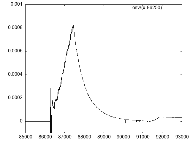
A really useful (and hackish) experiment is to divide the signal by a linear function, to poke with linear components.


Signal divided by linear function

The envelope divided by (x - 86250)


What emerge is that, once divided by x, the segment is markedly linear. This is really good, as it seems to suggest that the segment is quadratic.

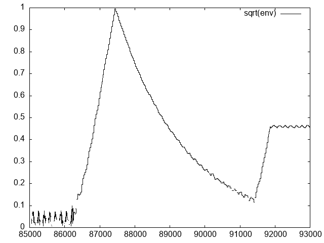
Let's go back at raw2plot.c and add a new column, that calculates the square root of the envelope. Patch is here.


Square root of the envelope

Square root of the envelope.


The linear behaviour of the square root is even more evident here.

Let's calculate the curve by finding the start and end samples of the segment. The maximum (1.0) is reached at sample 87427, while the signal appears to start (hard to tell given noise) at around 86275.

We have then that:

s = (1.0 - 0.0) / (87427 - 86275) = .000868

and

env(t) = V * s^2 * x^2

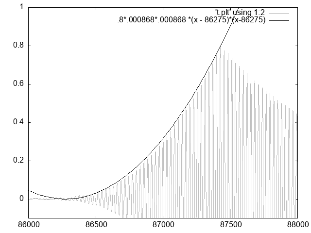
Let's try this against the signal:

$ gnuplot
gnuplot>  plot [86000:88000][-.1:1] 'envtest0.plt' \
using 1:2 with lines, \
.8*.000868*.000868 *(x - 86275)*(x-86275)

Fitting of rising segment with a parabola

Fitting of rising segment with a parabola.


It is a good fitting, apart from noise and some offset at the start.

As our goal is not a precise reproduction of the wave generated by the DX7 – this will likely require an analysis at the hardware level – but a characterisation of the envelope, this fits well enough.

Putting it all together

We now have enough data to reconstruct the envelope of ENV TEST#0.

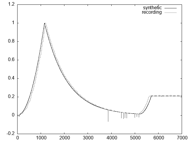
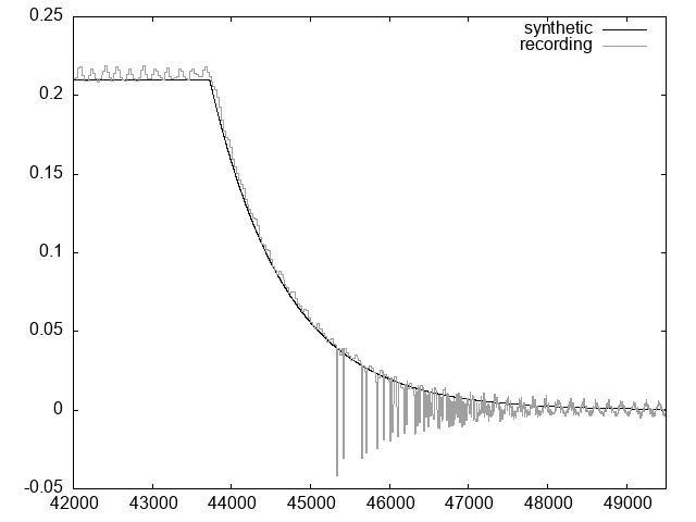
envtest0.c is a simple program that simulates the DX70 envelope at rate 50 using the equations we just found and recreates the original recording. Its output can be printed by gnuplot.


Match1 Match2

Comparison of envtest0.c output ("syntehtic") versus envelope of the recorded sound.


As you can see, the result is incredibly close. There's a lag of about 1000 samples (or 22usec) between on the start of segment three, which is probably due to an incorrect calculation of level 50.

Conclusion

We finally found out more about the DX7 envelope, and we were able to recreate an envelope based on our measuring.

This is not all is needed to simulate completely the Envelope Generator of a DX7. Information lacking is:

  1. How the parameters s and d change when rate changes.
  2. What's the output value for all the levels.

The Yamaha DX7 Envelope Generator, part three.

Part two is here

Extracting the envelope.

We concluded part two finding out that the DX7 envelope generator's curves were:

  1. non linear, apparently exponential.
  2. rising faster than they were decreasing.

Let's try to find out if the curves are indeed exponential.

Before we proceed, let's modify our tool to plot only what really interests us: the envelope. This patch to raw2plot.c adds a crude envelope detector: it tracks the delta between two samples to detect a local maximum when the derivative of the signal changes sign from positive to negative.

The output will now contain two columns: the first one is the signal, the second is the envelope.

$ ./raw2plot < envtest0.raw > envtest0.plt
$ gnuplot
gnuplot> plot 'envtest0.plt' using [1:3] with \
lines

Now that we have the envelope extracted, we can finally try to understand more about it without being distracted by the wave's oscillations.


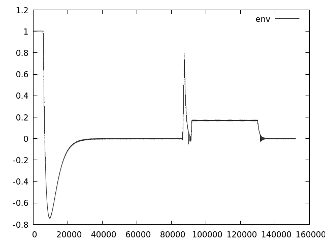
Plot of recording's envelope

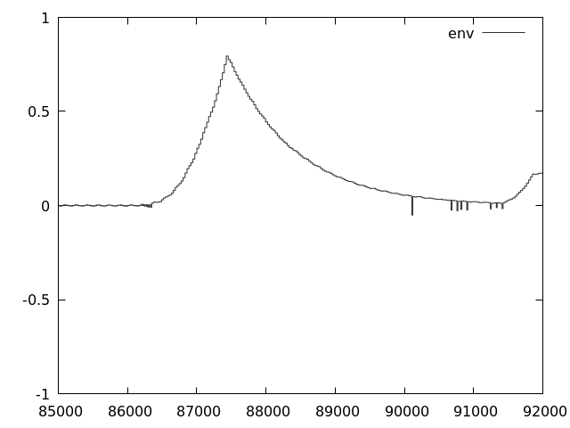
Plot of the first two segments envelopel

Our recording and the first two segments of our signal after being processed by the envelope detector.


Normalising the envelope

The record we're using has maximum volume at 0.794. In order to make our calculations more generic, let's normalise this by setting the maximum to 1.0.

[This patch] adds support for an passing an optional normalisation factor to raw2plot.

This command:

$ ./raw2plot .794 < envtest0.raw > envtest0.plt

will produce the same graph as above, scaled so that value 0.794 will become 1.0.

For the rest of this article we'll be using the normalised envelope.

Searching for exponentials.

A quick and immediate way to check for exponential curves of the form exp(x * T) in the envelope is to plot in logscale. this is easy in gnuplot, using set logscale y.

$ gnuplot
gnuplot> set logscale y
gnuplot> plot 'envtest0.plt' using [1:3] with \
lines

This will produce a log-linear plot of the envelope: abscissa unmodified but ordinate in log10.


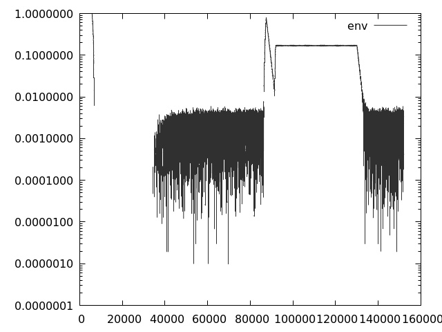
Plot of recording's logscale evnelope

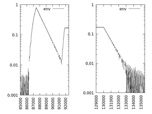
plot of recordings's logscale envelope edges

Logscale (base 10) plot of the envelope, and details about segments.


It emerges clearly that the decreasing edges are linear in log scale: this means they're pure exponential. The increasing segments are more complicated.

Decreasing segments

We have finally collected enough data to find the equation of one element of the DX7 envelope generator: the decreasing segments.

The first segments reaches the maximum (1.0) at sample 87427, and decrease linearly until sample 91410. Near the zero the graph is polluted by recording noise, so we take another earlier sample point and find the decay constant. Let's note that at sample 89640, output is circa .1.

The slope of the segment in the log-linear plot is:

d = -log(.1 / 1) / (89640 - 87427) = 0.00104

d is the decay constant we're searching for, and a decreasing envelope in DX7 at rate 50, with a sampling rate of 44100 sample/secs, will behave as:

env(t) = V * exp(-d * t)

where V is the maximum level reached by the envelope.

The time constant for rate 50 of a decreasing envelope is:

T = 1/d = 961.1 samples

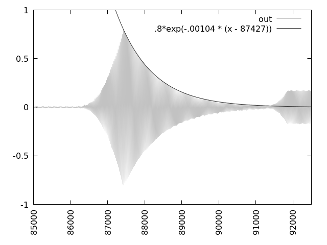
Let's prove our theory comparing or wave with the exponential 0.8 * exp( -d * (x - 87427)):

$ gnuplot
gnuplot>  plot [-1:1] 'envtest0.plt' using 1:2 \
with lines, .8*exp(-.00104 * (x - 87427))

Fitted exponential


Our curve matches perfectly the decreasing envelope!

Conclusions

What we have so far is a characterization of the decreasing segment of an envelope in a DX7, with precise measurement for rate 50 (the one recorded).

In part four, we'll focus on the rising segments.

Updated sourcecode for rawp2plot.c is in the 'part3' branch of this GitHub project.

Part four is here

The Yamaha DX7 Envelope Generator, part two.

Part one is here

A closer look at an operator envelope.

Let's begin our understanding of the envelope generators by trying to answer the easier question: what kind of shape the envelope segments have.

As already anticipated, we'll have to look at the DX7 output, and in order to have a rational analysis we'll have to control it somehow, to isolate the part we want to study.

Let's do this by creating a simple voice and uploading it to the synthesizer. The voice (ENV TEST#0) will have one operator active, with a simple envelope. The envelope will go from 0 to 99, 99 to 50, 50 to 80, 80 to 0. On a constant, slow rate. Fast enough that can be recorded quickly, slow enough that the curve can be seen.

The rest of the voice should be configured as flat as possible, with no fancy settings to avoid complicating our analysis.

Creating a voice.

In order to create a voice we need to create a MIDI System Exclusive message that contains the voice in the Packed 32 Voice format. It is a format that stores all 32 voices of a DX7 in 4096 bytes.

The structure of the SYSEX message and the bulk voice format can be both found in the DX7s Owner's Manual.

genrom.c is a simple application that write to standard output a packed 32 voices bulk SYSEX message for the Yamaha DX7. The first voice in the set is ENV TEST#0, all others are empty).

The basic characteristic of the voice can be seen in this code excerpt:

v.ops[0].eg_rate[0] = 50;
v.ops[0].eg_rate[1] = 50;
v.ops[0].eg_rate[2] = 50;
v.ops[0].eg_rate[3] = 50;
v.ops[0].eg_level[0] = 99;
v.ops[0].eg_level[1] = 50;
v.ops[0].eg_level[2] = 80;
v.ops[0].eg_level[3] = 0;

Note that we're only setting to non-zero the first operator. All other operators are essentially turned off. The algorithm used (i.e., the connection map of the operators) is 32, i.e., all operators go directly to output, no one modulates any other operator.

After compiling the above program, we can finally create a file to send to the synthesizer:

$ ./genrom > envtest.syx
$ file envtest.syx 
envtest.syx: SysEx File - Yamaha

We now have a file slightly bigger that 4k that contains the set of voices just created. The next step is sending it to the synthesizer.

Uploading a voice.

Uploading the set of voices to the synthesizer is also straightforward.

All we need to do is turn the synthesizer on and setting memory protection to off (the synthesizer manual will explain how to do that). Once this is done, you can send envtest.syx from your computer with the amidi ALSA utility:

$ amidi --send envtest.syx -p <port>

<port> should be substituted with your midi device ALSA port. If you don't know it you can find it with amidi -l. Should be in the form hw:[0-9]+,[0-9]+,[0-9]+.

If this is successful, you should see that the voice names in your DX7 have changed. They'll be all empty except from the first one, which will be ENV TEST#0.


ENV TEST#0 loaded

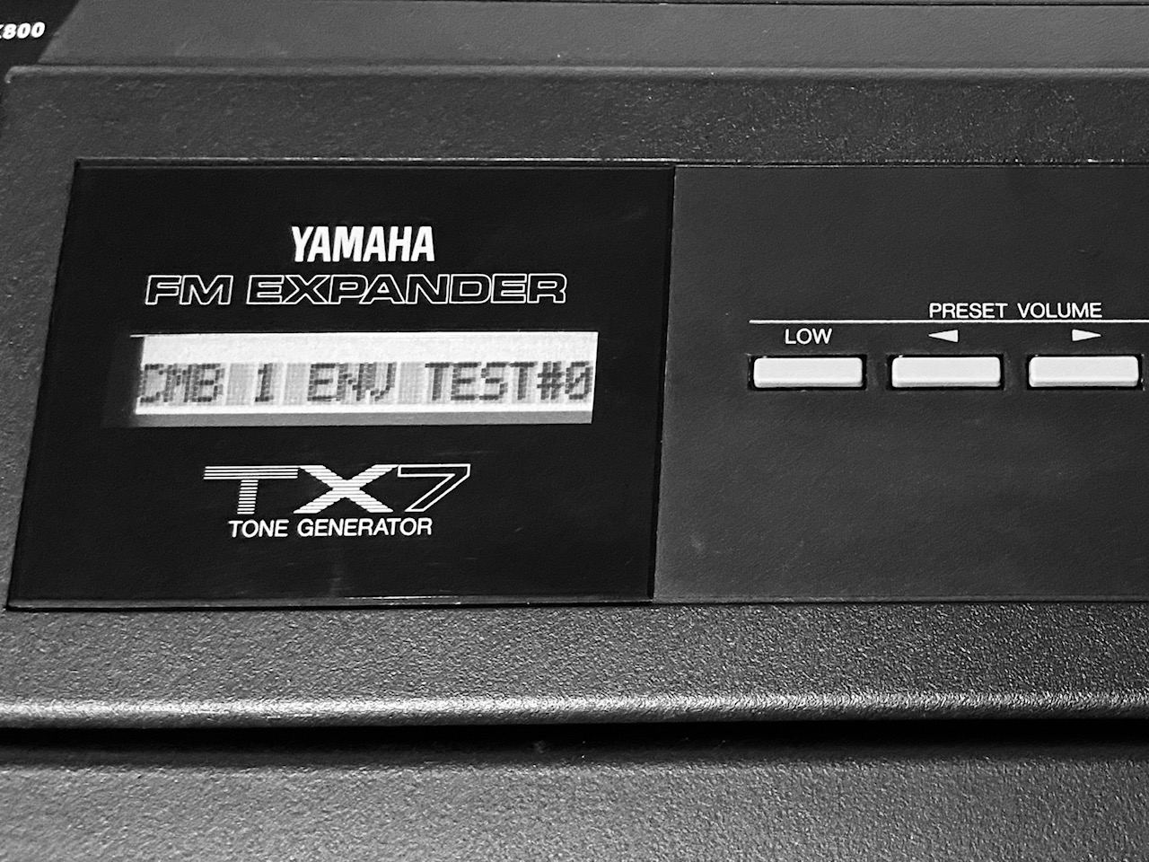
ENV TEST#0 loaded on a Yamaha TX7, a desktop version of the DX7.


We now have our test voice loaded in the synthesizer. All we need to do is playing a note and recording the sound.

Recording a voice.

This step is also very basic. All that is required now is to connect the output of the DX7 to the microphone input of the computer, and record the output of a single note in raw format:

$ arecord -f FLOAT_LE -t raw -c 1 -r 44100 envtest0.raw

envtest0 contains a sequence of 32-bit floats (on a little-endian machine), one per each sample, -c 1 specifies mono recording.

It can be played back using aplay:

$ aplay -f FLOAT_LE -t raw -c 1 -r 44100 envtest0.raw

Now that we have a recording of the sound, we can finally start analysing it.

Plotting the voice.

Let's write a basic tool that we'll hack as we go: raw2plot.c is a simple C program that takes a raw file and converts it into a format understood by gnuplot.

Once it is compiled, we can generate a gnuplot output and plot it.

$ ./raw2plot < envtest0.raw > envtest0.plt
$ gnuplot
gnuplot> plot 'envtest0.plt' with lines

And you should see a window appear with your wave plotted.


Plot of recording

Plot of the signal

plot of the first two segments

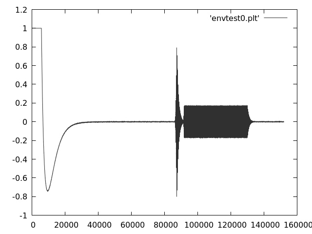
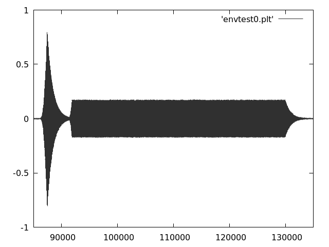
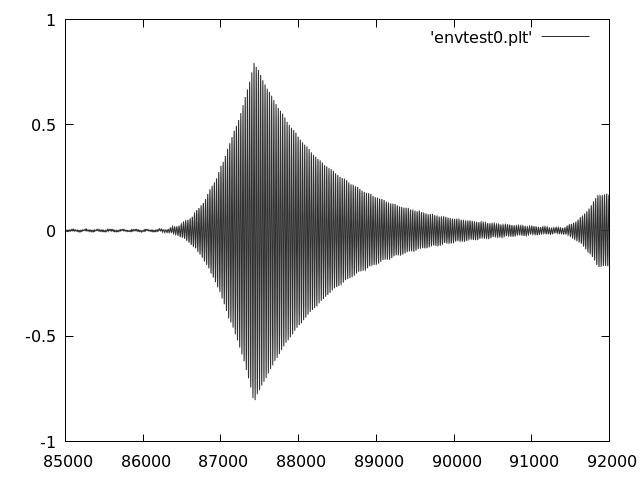
gnuplot output at three different zoom levels: full recording, the signal recording, the first two segments of the envelope.


As you can see, something quite strange is going on at the start of the recording, most likely at the sound card level. After giving it some time for settling, a key is pressed and the sounds is recorded. As expected, the envelope goes to level 99, then to 50, and then to 80, and finally back to zero.

Even with a single plot we can derive the following conclusions:

  1. The envelope is not linear. Appears exponential, and at parity of rate the rising of the envelope is faster than the decay.
  2. Levels are not linear: level 50 is very close to zero, and level 80 is less than half of level 99.

In the next part we'll attempt at characterising this plot.

Source code and samples

All source code and samples used in this post are in the 'part2' branch of this GitHub project.

Part three is here

The Yamaha DX7 Envelope Generator, part one.

Silence, sine waves and trigonometry.

The Yamaha DX7, an FM synthesizer released in 1983, should need little or no introduction. Its sound can be heard throghout most of mid-to-late 1980s music.

If you're new to FM synthesis, I'd suggest reading Chowning's paper that introduced the concept: it's a fascinating and inspiring read.

The DX7 has six operators. Each operator is an oscillator with two inputs (amplitude and pitch), with the output sine wave modulated by a per-operator envelope. The fundamental operation of FM synthesis consist in using the output of an operator to modulate the pitch of another (or itself, referred to as feedback). An additional global envelope modulates the pitch of the note being played.


Two operators scheme

The basic operation of FM synthesis: one operator (Modulator) modulates the pitch of a second operator (Carrier) that produces sound. (Source)


A DX7 voice, or instrument, specifies each operator's (relative or absolute) pitch and amplitude, and defines how they're connected to each other, and which operator's output becomes sound. There are other parameters, but the fundamental characteristic of a voice is defined by the parameters above.

The Yamaha DX7 can hold 32 voices. It is possible to create and use new ones – it's a programmable synthesizer after all – and the never disappointing Internet has many new voices available for download.

The preset voices (that range from Piano, to Marimba, to Bass) show how flexible this synthesizer is. It is in the nature of curious people, then, to look at each voice and see how they're made. These are not samples after all, the operators synthesize these complex sounds from silence, sine waves and trigonometry!

This is precisely the beauty of FM synthesis: its theory and basic implementation are simple, and few lines of code produce powerful and unexpected results.

Analysing a DX7 voice.

In order to look at voices, we need to fetch them and look at their internals.

Both operations are quite easy. You can instruct the synthesizer to dump all 32 voices in bulk over MIDI and in Linux you can easily save them using amidi --receive. The format is quite simple, and well specified in the DX7 manuals.

Understanding how those parameters translate in physical characteristic is a bit more complicated.

The DX7 operator configuration is mostly in settings that go from 0 to 99, and understanding how these translate into sound production (pitch, amplitude) requires some fair amount of reverse engineering.

The operators connections (algorithms) and the frequency at which they operate are well known and easy to understand.

What's hard, and yet fundamental for characterising a FM sound, is understanding the parameters of the envelope generators.

Understanding envelopes.

As already said, there are seven envelope generators in a DX7 voice. Six for each operators, modulating amplitude, and one global, modulating the pitch.

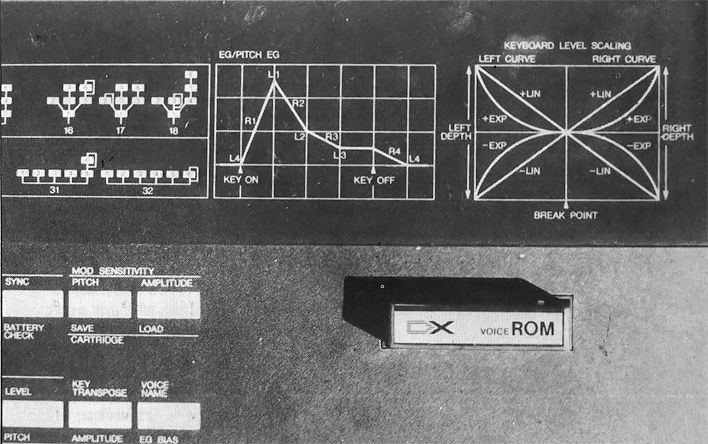
An envelope in a DX7 has four segments. Three for attack (start of note to sustain) and one for the decay (end of sustain to end of sound). Each of these segments are configured by two paramenters, level and rate. Level (0-99) is the amplitude reached by the segment, rate (also 0-99) specifies how fast it will get there.


DX7 Envelopes

A DX7 envelope scheme as printed on the synthesizer itself. (Source)


At this point a lot of question arise, some make sense, some might not.

  1. What kind of curve has each segment? (linear, exponential, other)
  2. How level progress from zero to maximum? (linear, exponential, other)
  3. How rate progress from zero to maximum? (linear, exponential, other)
  4. How level (amplitude) is interpreted when used to modulate frequency of another operator? I.e., what amplitude is required to modulate the operator frequency by 1 Hz?

In order to get these answers, we'll have to look at waves.

Part two is here

Overview of a MH System.

In a system running MH, each process has its own local bus. The kernel mantains a global list of devices.
If it has enough permissions, a process can add a device to its own local bus and use it.

There are three broad kinds of devices:

  • User devices. These are devices created by processes, and it's the only inter-process communication mechanism present in the system.
  • Kernel Devices. These are special devices created by the kernel, used to provide kernel services to a process – timers, memory allocation, etc.
  • Hardware Devices. This is a mapping from real hardware to I/O devices. A special hardware device is the platform device, which gives access to the whole machine to a process.

The Process-Device interface

A process and a device communicate using three mechanisms:

  • IO ports. Similar to Intel I/O space, a process can write, or read, an inline value to a specified port of the device. The meaning assigned to these action is device specific.
  • DMA. A device can read or write directly to a process space. An I/O MMU mechanism is present so a device can only access memory explicitely exported by the process.
  • IRQs. A device can send interrupts to a process.

The MH Process/Device Interface

MH Process/Device Interface


Virtual Memory Mappings States in MH

I like to go back at the drawing board. Gives you opportunity to think, to look at what you have, and to reconsider what you need.

The MH's memory map system (pmap) move to machine independent part – similar to the change that did this for the CPUs and IPIs management subsystem) – offered such opportunity for this key component.

Compared to other memory subsystems I have seen in the past, I always thought of MH's virtual memory to be extremely simple. So, before blindly porting a code that shows signs of ageing and where different strata starts emerging, I decided to look at the states of a virtual mapping. Afterall, I expected it to be simple.

The first layer was easy to draw:

Top-level view

I.e., a user PTE is either unmapped, or mapped to a hardware I/O page, or mapped to a memory page. The dot points to the default state, that is at start we expect all virtual memory to be unmapped.

Of course, it's not that simple. Mapped pages can be wired by the kernel, i.e. made unable to be unmapped by userspace programs. The act of wiring a page is still initiated by the user, by exporting a memory to a hwdev. Wiring is needed because exporting a page to a hwdev allows doing DMA on that memory region.

An updated graph will look like this:

Refinement 1

Which is – still – very simple. The square represents what's left of the node called Mapped in the earlier figure.

But this is ignoring something really important: copy-on-write. MH supports forking of processes. As essentially any other OS who supports paging, it uses copy-on-write as an optimization for duplicating address spaces: instead of being copied, the memory is shared but set read only.

When a process tries to write to a shared page, it will generate a page fault, which will be forwarded as an interrupt to the process. It is userspace responsibility to create a new page, copying its content, and substitute the read-only shared mapping with a writable copy.

This then means that this state, RO Shared, can only be changed by userspace by unmapping it. There is an exception of course, which is due to an optimization: when all processes but one have all created their own copies, the page is effectively not shared anymore, and can be re-made private.

An important note to add at this point is that copy-on-write is the only case in MH where memory is shared between processes.

Updating the graph yields:

Refinement 2

This starts to look interesting, and messy enough to look real. It is not complete, yet.

As said earlier, the read/write information is lost during the process of copy-on-write, so in the current implementation the page returns into being private, but read-only, no matter the original state. This is not a problem, though, as long as the userspace process can handle unexpected RO page faults by fixing them back to writable. The MRG system library supports this.

Adding details about R/W state brings to a more complete graph, with clear signs of state explosion:

Refinement 3

Is this complete? Of course not. We're missing information about the executable state of a page. A page can be executable or not, and as long as it is private and not wired its state can be changed.

I won't display this, though, as it is essentially an orthogonal state with regards to the lifetime of a page.

History and motivation

As opposed to other kernels and microkernels – probably –, MH is based on a completely random ideology, picked arbitrarily, in a Cambridge pub, after evidently too many beers.

Unimpressed by the lack of shape in modern software, some day in 2014 I thought that it would be really cool to build a system made of tangible abstractions. A system described in terms of objects that can be very easily understood would be – I decided – very pleasant to play with, and to use as a base for complex systems!

A system built with a single tangible abstraction – I continued – would be even more pleasant and simple!

Abstractions and inspirations

The search for that abstraction wasn't easy. Ruled out exokernels and L4 pretty quickly, I decided to have a look at the classics.

Mach is beautiful, if you don't look at the code. I had my share of fun hacking it and it is definitely made of abstraction that are easy to tinker with, and that have proven themselves definitely capable of building complex systems since 1985. But its abstractions are not clearly linkable to well defined existing objects: every introduction to Mach needs to explain what is a port, and port sets, and port rights, and memory objects.

The beauty of Mach, and what I wanted to take from it, is that it defines its basic abstractions, and a set of principles, and maps every possible activity of a computer into these abstractions. Mach calls you into experimenting with it. That's what I wanted to have.

Another system I wanted to steal from is the UNIX operating system. "Everything is a file", despite being a lie since at least the addition of networking, is an incredibly powerful principle.

The early UNIXes loosely presented to the user a model of what a machine was at the time: a single cpu, interrupts (signals), a disk (filesystem), and a terminal.

World views

The world of a userspace program in Mach is made of ports and memory objects, in UNIX is that of a simplified computer. I liked the latter. A computer is understandable by a programmer.

I decided to move toward a system that presented something familiar, a UNIX process model, in a world where a computer is not made only of internal disks and not many terminals are around. Furthermore, I wanted to achieve an extensibility similar to that of Mach by letting userspace processes export the same abstractions that the kernel uses to export its services. And finally, I wanted a system fun to use and extend.